In-line testing and calibration of radar components
Modern technology makes driving easier, decides in milliseconds on emergency braking and thus increases safety in the car.

However, the sensors used must meet the very highest safety criteria. The trend is towards radar sensors that scan the space around the car in different frequency ranges. In order to safely calibrate such high-frequency components and subject them to a reliable final inspection, extensive know-how is required in the testing facilities. ENGMATEC, a specialist for assembly and test lines with decades of experience, offers an interesting concept here. Whether individual test chambers or integrated into production, the specific requirements of high-frequency sensor technology must always be taken into account.
Radar sensor technology in motor vehicles
At the moment, car manufacturers like to use radar sensors for medium distances. The advantage over optical systems is that they can "see through" even in fog and other optical impairments. The sensors usually operate in the splash water area at the front and rear of the car, i.e. in a very adverse environment. They are therefore completely sealed. Depending on the application, the operating frequency varies between 24 and 70 GHz. The range of the radar sensors also varies. Depending on the design, there are different viewing ranges from 2 to 200 m, often referred to as near-field, mid-range and long-range sensors.
A distance of approximately 45 m is defined as the so-called middle range. The sensors are used as complete modules, consisting of transmitter and receiver, but can also be discrete components, i.e. transmitter and several antennas. This is the best way to implement vehicle-related requirements.
Since radar technology in modern automobiles has to work together with numerous other components, and since the environment can also have numerous adverse effects, a practical test of the safety components is literally vital.
Operating conditions
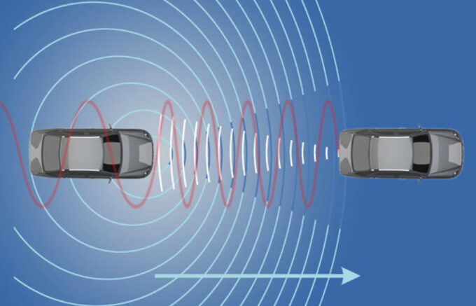
Radar technology is based on the transmission of radio pulses and the subsequent collection of the reflected radiation. It is analyzed, evaluated and the result is the basis for the decision of the assistance system. The higher the transmission frequency, the shorter the wavelength and the better the resolution of the sensor. Better said, the higher the frequency, the smaller individual objects can be detected. Distance measurement is independent of the frequency and only dependent on the fixed speed of light. Classically, the transit time between the transmitted pulse and the captured echo is measured, halved (outward and return paths require the same time), multiplied by the speed of light, and the distance to the target object is determined. Another method is the pulse Doppler principle for velocity measurement. It is based on the fact that the frequency of the reflected wave changes when a relative velocity is present. Direct relative velocity measurement is a key advantage of radar measurement. However, this requires an analysis of the frequency spectrum. However, interfering pulses such as radio pulses from mobile phones, WLAN and radio keys must be safely faded out in the process.

Modern components allow the entire sensor system, including interference filter, to be installed in the smallest possible space. Fast computers provide finished signals for further evaluation. However, all this must also function reliably mechanically over a long period of time. The application in the motor vehicle is one of the most demanding at all. Siberian cold to midday heat over "red-hot" asphalt must be endured just as much as moisture, salt, vibration, shock, dust and much more. Here, only a sophisticated testing technology that covers all areas of practice can lay the foundation for sound quality assurance.

Calibration and testing
The properties of electronic components and assemblies are also subject to statistical fluctuations. In order to produce sensors of consistent quality, calibration to a standard measurement is therefore necessary. If, for example, 70 m is to be measured, this must of course be tested and adjusted beforehand for each sensor. ENGMATEC therefore offers test modules that measure the radiation intensity and delay and attenuate the signal in the runtime according to the distance to be tested. For the radar sensor under test, this appears as if an obstacle appeared 70 m away.
To exclude interference during the test, the test area must be specially shielded. External influences that affect the test must be taken into account, such as mobile phone radio from employees or interference pulses from frequency converters. Interference pulses are also generated by parallel operation of several test systems. Internal radiation from the test operation must also be shielded so as not to impair the environment. For safe operation, the test environment and the environment must not influence each other. All test equipment can be used both as a stand-alone module for semi-automatic operation and integrated into a production line. Last but not least, the leak tightness of the assemblies and housings must be tested. For this purpose, pressure is applied to the test specimen in a vacuum. If a pressure loss is detected when the pressure is measured, this indicates the presence of leaks in the test item (Closed Components Test).
Practical
So what do such test facilities look like? A shielded test cell that has proven itself in practice and in which user-specific test equipment can be installed can accommodate assemblies between 90 x 63 x 20 mm (L x W x H) and 120 x 85 x 28 mm.
For a shielded PCB test in a defined test environment with a pre-assembled radar PCB group, another test box provides space. For pure high-frequency tests, special absorber materials (Fig. 6), radar chambers and programmable frequency simulators are available.
A milled delay line enables a defined time delay of the signals. The signal is returned within a few nanoseconds, corresponding to the real running distance in practice.
ENGMATEC http://www.engmatec.de
Editorial office Stutensee http://www.rbsonline.de


